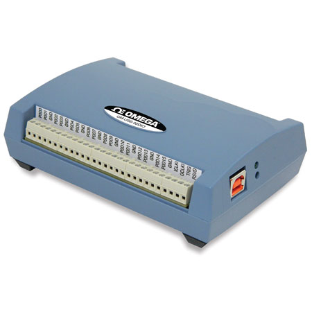


OM-USB-32DIO详细介绍
OM-USB-32DIO
数据采集 ? USB, RS232, RS485和Ethernet数据采集... ? OM-USB-32DIO
32-Channel High Speed Digital I/O USB Data Acquisition Module
32 Bits of Bidirectional TTL Digital I/O
Pattern Detection and Generation
Input Scan Rate up to 8 MS/s
Rate up to 8 MS/s
Independent Input and Output Scan Clocks
24 mA Source, 10 mA Sink Output Current
External Trigger and Clock Inputs
产品描述
The OM-USB-32DIO provides 32 bits of high-speed digital I/O, and features independent input and output scan clocks, hardware and software triggering, and pattern detection/generation.
Digital I/O
The 32 DIO bits are available as two 16-bit ports that are bit-configurable for input or output. Each port is configured independently, so both software polling and hardware scanning operations can be performed at the same time. When performing software polling, the port can contain any combination of input or output bits. When performing hardware-paced output scans, all bits in the port must be set for output. For input scans, however, the current state of any bits in the port that are configured for output are read.
Digital Output Scanning
Either port can output a 16-bit digital pattern. The pattern is d at a rate up to 8 MS/s, and clocked using the output scan clock. Use both ports to output a 32-bit digital pattern. Data from one port is read and stored in the FIFO buffer until the second port is read. Both ports are output simultaneously on the rising edge of the next pacer clock signal.
Data Transfer
The OM-USB-32DIO uses a delay between the output scan clock and the data transfer pin, which allows an external device that is receiving the data to know that the data is stable at that point, and ensures a coherent data transfer between devices.
Pull-Up/Down Configuration
The DIO bits can be pulled up to 5V or down to 0V through 47 kO resistors via onboard jumpers.
Clock I/O
Users can pace input scanning operations with the onboard input scan clock or with an external signal. The input clock frequency is 8 MHz, maximum. A duty cycle of 50% is maintained when the internal input clock paces operations. When using an external clock, the signal is output immediately after the external clock input is received.
Triggering
Digital and pattern triggering are supported. The TRIG pin is used for external TTL level triggering, and can be used to trigger input or output scans. Trigger latency is less than 1 μs. The trigger mode is software-able for edge or level sensitive, and high or low logic. Either digital port can be used for pattern triggering. A scan is triggered when a specified pattern is detected. Specific bits can be masked or ignored. Trigger latency is 1 scan clock period. You can input or output a digital pattern under the timing control of a clock signal.
Software
The OM-USB-32DIO module ships with an impressive array of software, including TracerDAQ®, a full-featured, out-of-the-box data logging, viewing, and analysis application. Driver support and detailed example programs are included for Universal Library programming libraries for Microsoft® Visual Studio® programming languages, and other languages, including DASYLab®, and ULx for NI LabVIEW® (comprehensive library of VIs and example programs compatible with 32-bit and 64-bit LabVIEW 2010 or later) and InstaCalTM installation, calibration and test utility-powerful solutions for programmers and nonprogrammers alike. These modules operate under Microsoft WINOOWs® VISTA/7/8/10 (32-bit and 64-bit) operating systems.
The OM-USB-32DIO data acquisition module is supplied with TracerDAQ software which is a collection of four virtual instrument applications used to graphically display and store input data and generate output signals:
? Strip Chart—Log and graph values acquire from analog inputs, digital inputs, temperature inputs and counter inputs
? Oscilloscope—Display values acquired from analog inputs
? Function Generator—Generate waveforms for analog outputs
? Rate Generator—Generate waveforms for counter outputs
TracerDAQ PRO is an enhanced version of TracerDAQ and is available as a purchased upgrade (SWD-TRACERDAQ-PRO). A comparison of some of the features included in TracerDAQ vs TracerDAQ PRO is shown on the PDF.
Specifications
DIGITAL INPUT/OUTPUT
Digital Type: TTL
Number of I/O: 32 (2 ports of 16-bits)
Configuration: Bit-configurable as input (power on default) or output
Pull-Up Configuration: Each port has two 47 kΩ resistors configurable as a pull-up or pull-down (default) with an internal jumper
Each jumper Configures 8 Digital Bits:
Jumper W3: Configures port 0 bit 0 to bit 7
Jumper W4: Configures port 0 bit 8 to bit 15
Jumper W5: Configures port 1 bit 0 to bit 7
Jumper W6: Configures port 1 bit 8 to bit 15
Digital I/O Transfer Rate:
System-Paced, Asynchronous: 33 to 8000 port reads/writes or single bit reads/ writes per second typical, system dependent
Synchronous: 0.022 Hz to 8 MHz, based on the internal clock speed of 96 MHz
Digital Input Pacing: Onboard clock, external input scan clock (ICLKI)
Digital Input Trigger Source: External single channel digital trigger (TRIG) or Pattern Detection
Digital Output Pacing: Onboard clock, external output scan clock (OCLKI)
Digital Output Trigger Source: External single channel digital trigger (TRIG) or Pattern Detection
Input High Voltage: 2.0V min, 5.0V absolute max
Input Low Voltage: 0.8V max, 0V recommended min
Output High Voltage: 4.4V min (IOH = -50 μA), 2.96V min (IOH = -24 mA)
Output Low Voltage: 0.1V max (IOL = 50 μA), 0.77V max (IOL = 10 mA)
Output Current: 24 mA source, 10 mA sink max per pin, constrained to 384 mA across all output pins (digital outputs, pacer clock outputs, and +VO)
EXTERNAL TRIGGER
Trigger Source: External digital; TRIG terminal
Trigger Mode: Software-able for edge or level sensitive, rising or falling edge, high or low level
Retrigger Mode: Trigger is rearmed after each trigger event
Trigger Latency: 100 ns max
Trigger Pulse Width: 100 ns min
Input Type: Schmitt trigger, 47 kΩ pull-down to ground with 33 Ω in series
Schmitt Trigger Hysteresis: 0.76V typ, 0.4V min, 1.2V max
Input High Voltage Threshold: 1.74V typ, 1.3V min, 2.2V max
Input High Voltage Limit: 5.5V absolute max
Input Low Voltage Threshold: 0.98V typ, 0.6V min, 1.5V max
Input Low Voltage Limit: -0.5V absolute min, 0V recommended min
PATTERN TRIGGER
Trigger Source: Port 0 or Port 1
Trigger Types: Above pattern, Below pattern, Equal pattern, or Not equal pattern
Trigger Stability: Digital port must be stable for 31.25 ns to be recognized as a pattern
Trigger Bit Width: Up to 16, adjustable through bitmask
Trigger Latency: Up to 1 scan period
CLOCK INPUT/OUTPUT
Terminal Names: ICLKI, ICLKO,OCLKI, OCLKO
Terminal Type:
ICLKI: Input scan clock input, active on rising edge
ICLKO: Input scan clock output, power on default 0V, active on rising edge
OCLKI: Output scan clock input, active on rising edge
OCLKO: Output scan clock output, power on default 0V, active on rising edge
Input Clock Frequency: 8 MHz max
Input Clock Pulse Width: 10.417 ns min
Input Type: Schmitt trigger, 47 kΩ pull-down to ground with 33Ω in series
Input Schmitt Trigger Hysteresis: 0.76V typ, 0.4V min, 1.2 V max
Input High Voltage Threshold: 1.74V typ, 1.3V min, 2.2V max
Input High Voltage Limit: 5.5V absolute max
Input Low Voltage Threshold: 0.98V typ, 0.6V min, 1.5V max
Input Low Voltage Limit: -0.5V absolute min, 0V recommended min
Output Clock Frequency: 8 MHz max
Output Clock Pulse Width: Minimum 62.5 ns at 8 MHz, but varies according to the sample rate; always maintains a 50% duty cycle when using the internal clock; when using the external clock, it follows the external clock input
Output High Voltage: 4.4 V min (IOH = -50 μA), 2.96V min (IOH = -24 mA)
Output Low Voltage: 0.1V max (IOL = 50 μA), 0.77V max (IOL = 10 mA)
Output Current: 24 mA source, 10 mA sink max per pin, constrained to 384 mA across all output pins (digital outputs, pacer clock outputs, and +VO)
Handshaking: The TXACK output will have an 83.33 ns delay from the OCLKO signal to ensure coherent data transfers between devices
Power
Supply Current, USB Source:
During Enumeration: lt;100 mA
After USB Enumeration: lt;500 mA
+VO Voltage Output Range: After USB enumeration: 5V, ± 5%
+VO Output Current: After USB enumeration: 24 mA max per pin, constrained to 384 mA across all output pins (digital outputs, pacer clock outputs, and +VO)
USB
USB Device Type: USB 2.0 (high-speed)
Device Compatibility: USB 1.1, USB 2.0, USB 3.0
USB Cable Length: 3 m (9.84') max
ENVIRONMENTAL
Operating Temperature Range: 0 to 50°C (32 to 122°F)
Storage Temperature Range: -40 to 70°C (-40 to 158°F)
Humidity: 0 to 90% RH non-condensing
MECHANICAL
Signal I/O Connector: 2 banks of screw-terminals
Wire Gauge Range: 16 to 30 AWG
Dimensions: 128.52 L x 88.39 W x 35.56 mm H (5.06 x 3.48 x 1.43")
Weight: 0.49 kg (1.08 lb)
产品编号 产品描述
OM-USB-32DIO32-channel high speed digital I/O USB data acquisition module
SWD-TRACERDAQ-PROTracerDAQ PRO Software
==================
OM-USB-32DIO
SWD-TRACERDAQ-PRO
OM-USB-32DIO
OM-USB-32DIO相关产品
OM-USB-32DIO技术文章
 898995850